Phone: +86-755-2357-1819 Mobile: +86-185-7640-5228 Email: sales@ominipcba.com whatsapp: +8618576405228

From Bare Board to Finished Product: A Guide to Box Build Assembly
Streamline your box build projects. We guide engineers and buyers through BOM management, mechanical integration, and bridging the gap between PCBA and final assembly
PCB TECHNOLOGY
OminiPCBA
12/9/20253 min read
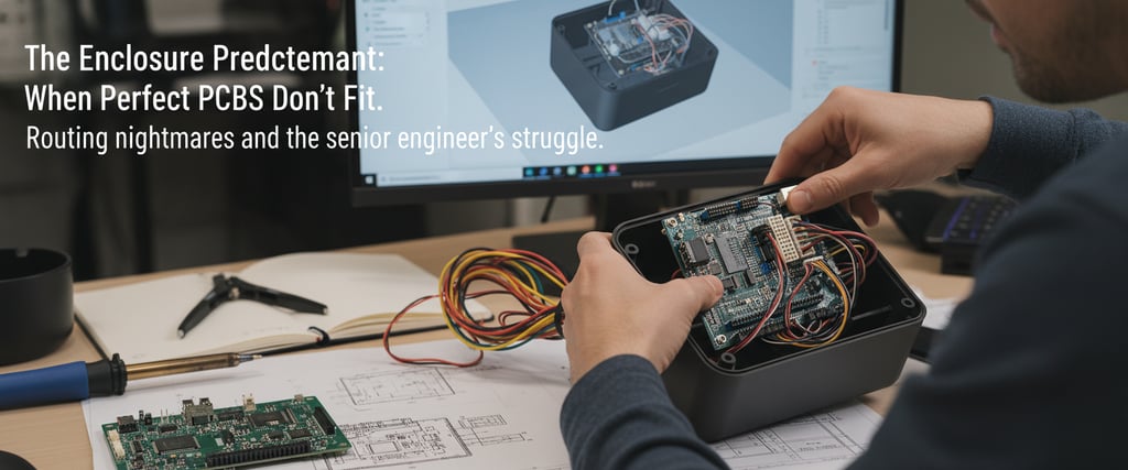
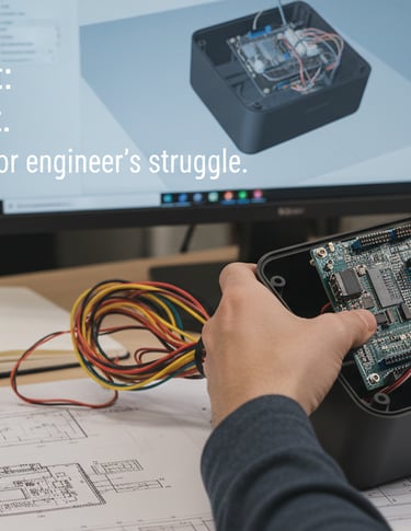
Engineers often spend months perfecting PCB layouts—optimizing impedance, managing thermal profiles, and ensuring signal integrity. However, as any veteran hardware developer knows, a flawless Printed Circuit Board Assembly (PCBA) is only successful if it integrates seamlessly into its enclosure and allows for efficient cable routing during mass production.
This phase is known as Box Build Assembly (or systems integration). It serves as the critical bridge between the PCB manufacturing process and a market-ready product. For procurement managers and hardware engineers, transitioning from board-level design to full mechanical assembly introduces new complexities.
Here is how to collaborate effectively with your Electronic Manufacturing Services (EMS) partner to ensure final assembly is as precise as the SMT process.
What Defines a Full Box Build?
A professional box build goes far beyond simply mounting a board into a housing. A comprehensive integration typically includes:
PCBA Integration: Secure installation of the populated circuit boards.
Cable & Wire Harness Routing: Precision interconnectivity between sub-assemblies.
Electromechanical Integration: Mounting switches, sensors, displays, and actuators.
Firmware & Software Loading: Flashing bootloaders, firmware, and custom configurations.
Functional Testing (FCT) & Packaging: End-of-line testing followed by retail-ready packaging.
Whether you are developing a rugged industrial controller or a high-density consumer wearable, the following Design for Assembly (DFA) practices will prevent production bottlenecks and quality escapes.
1. Create an Exhaustive Bill of Materials (BOM)
In standard PCB fabrication, a BOM covers resistors, capacitors, and ICs. For a turnkey box build, your documentation must expand to include every physical element of the device.
Production lines often stall due to "minor" missing items like a specific Loctite grade or a 2mm nylon washer. Your expanded BOM must include:
Consumables: Adhesives, cable ties, heat shrink, and thermal interface materials (TIM).
Mechanical Hardware: Screws (with torque specs), nuts, standoffs, and spacers.
Packaging Materials: ESD bags, foam inserts, user manuals, and serial labels.
Pro Tip: If a component isn't on the BOM, it won't be sourced, and the assembly line will stop.
2. Prioritize 3D Modeling and Mechanical Tolerances
While Gerber files are the industry standard for PCB manufacturing, they are 2D representations. For box builds, providing 3D CAD models (STEP files) is non-negotiable.
3D models allow your manufacturer to verify physical clearances before investing in expensive tooling. For instance, if you are utilizing rigid-flex PCBs to fold around a battery, the bend radius and internal spatial constraints are critical. Accurate modeling ensures that components won't interfere with enclosure ribs or screw bosses when the unit is sealed.
3. Design for Assembly (DFA) Optimizations
Electrical performance is the priority during layout, but for box builds, you must design for the technician (or robotic arm) performing the assembly.
Consider the mechanical trade-offs: while SMT components maximize density, through-hole connectors are often preferred for external I/O because they offer superior mechanical anchorage against "plug-unplug" stress.
Key DFA Checkpoints:
Is there sufficient cable slack to facilitate easy connection before the board is secured?
Are connectors accessible for testing probes and assembly tools?
Can you standardize hardware? (Using two screw types instead of ten reduces assembly time and error rates).
4. Define "Golden Samples" and Functional Testing (FCT) Protocols
A vague request to "test the unit" is a recipe for quality issues. You must define precise "Pass/Fail" criteria.
While Automated Optical Inspection (AOI) and In-Circuit Testing (ICT) validate the PCBA, a box build requires comprehensive Functional Circuit Testing (FCT). Provide your manufacturer with a "Golden Sample"—a verified, perfect unit that serves as the manufacturing benchmark. Additionally, document specific wire routing paths and torque settings to ensure consistency across high-volume batches.
5. Establish Continuous Feedback Loops
The first production run is a learning curve. Establish a feedback loop where the assembly team can provide DFM (Design for Manufacturing) insights. If moving a capacitor 2mm allows a technician to secure a screw 30 seconds faster, that insight can lead to massive cost savings and improved yields over the product’s lifecycle.
Partner with OminiPCBA for Complete Systems Integration
At OminiPCBA, we know you aren't just building a circuit board; you’re launching a product. We manage the entire manufacturing ecosystem—from complex multi-layer PCB stack-ups and component sourcing to final mechanical box build assembly.
Our engineering team bridges the gap between electrical design and mechanical reality, ensuring your hardware is built to spec, tested rigorously, and delivered to market on time.
Related Articles
Contacts
Email: sales@ominipcba.com
Mobile: +86-185-7640-5228
Copyright © 2007-2026. Omini Electronics Limited. All rights reserved.
Head Office: +86-755-2357-1819
Services
Your China turnkey partner for electronics manufacturing. We bridge design to delivery by leveraging the Shenzhen electronics ecosystem for precision engineering and streamlined PCBA supply chain logistics.
Ready to Build?
Get a comprehensive quote within 24 hours.
